Section Diagram
断面図
Danmenzu
CATEGORIES
Section diagrams are auxiliary diagrams showing parts that are not visible. Invisible parts in a three dimensional object are shown by hidden outlines (broken lines) but if too many are used, the blueprint becomes complicated and difficult to read. Therefore, section diagrams are used. By using a section diagram, we can visualize the shape of the invisible parts. The invisible parts are displayed by visible outlines (thick continuous lines). The different types of a section diagram are full section and half section as well as offset section, revolved section, removed section and part section. For example, the external shape of a relatively simple object would be shown as a full section while a complex object would be shown as a half section. Consequently, we need to consider the shape of the object we want to represent in choosing the most suitable section diagram.
When drawing a section diagram, the hidden outline is omitted and we use hatching (diagonal lines) in the cross section part to indicate that it is a section view. Hatching refers to fine continuous lines which, in principle, move upwards to the right at an angle of 45 degrees towards the visible outline. Depending on the object, it may sometimes be better not to do a section diagram. With a JIS mechanical blueprint, for example, it is recommended that, in principle, the absence of longitudinal cross-sections for axles, pins, keys, bolts, nuts, washers, screws, locking screws, rivets, ribs, vehicle arms, and gear teeth, etc. in diagrams, is easier to understand.
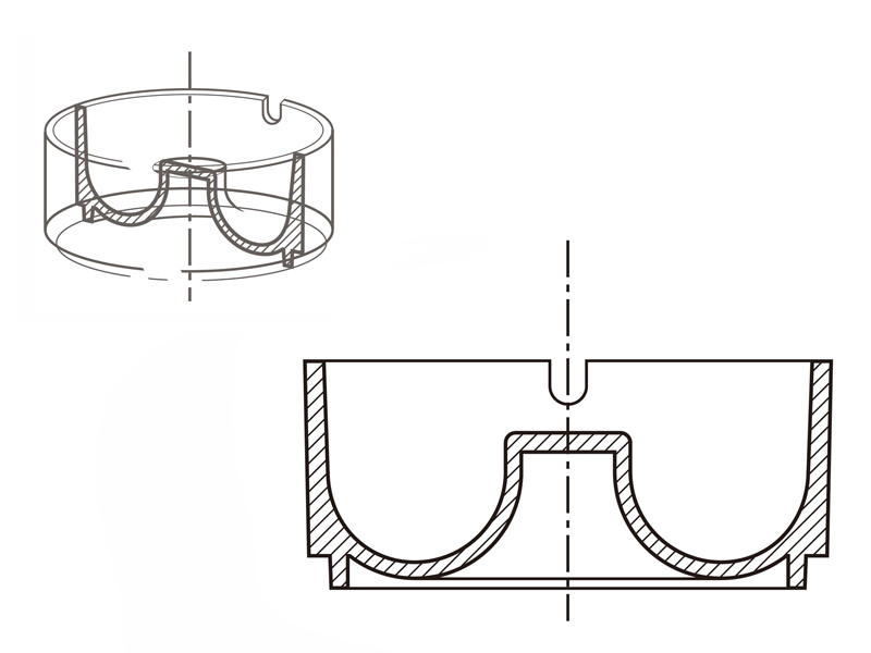 Full section
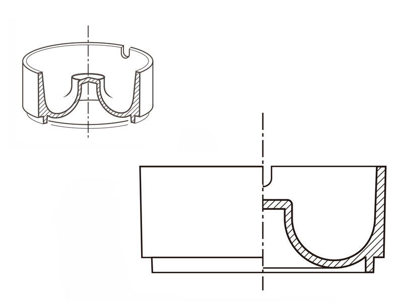 Half section